BESS Components Explained: Battery, BMS, PCS, EMS, Thermal Management, and Safety Systems
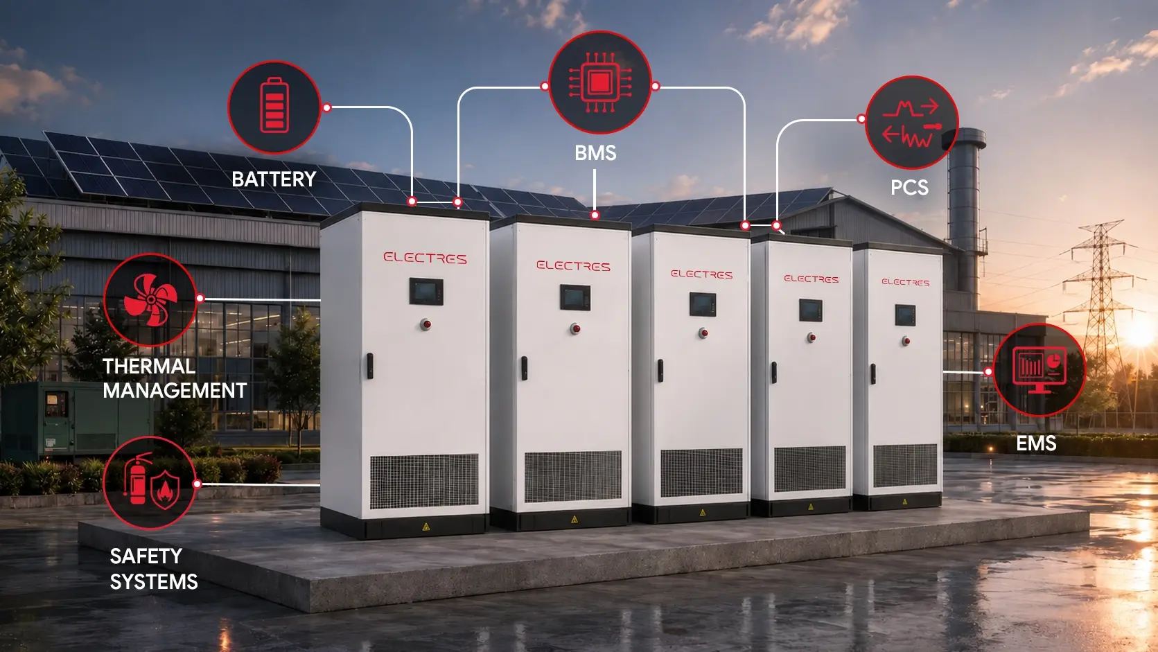
Battery Energy Storage Systems (BESS) have become a critical part of modern energy infrastructure. Organizations are now investing in Battery Energy Storage Systems (BESS) to improve power reliability, optimize energy use, support renewable energy integration, and better manage electricity costs.
However, the performance of a BESS depends on much more than the battery itself. The performance of a BESS depends on how effectively components such as the Battery Management System (BMS), Power Conversion System (PCS), Energy Management System (EMS), cooling systems, and safety controls work together.
Understanding these components allows teams to compare solutions, assess technical capabilities, and select a system that meets operational requirements. Evaluating a Battery Energy Storage System needs a clear understanding of how each component contributes to performance, reliability, and long-term system integration. This guide provides BESS components explained from a practical perspective. It explains the role of each major component, how they interact, and what to consider when evaluating a Battery Energy Storage System for commercial or utility-scale applications.
The Battery Subsystem: Where Energy Is Stored
Although the battery is at the center of every Battery Energy Storage System, it does not determine system performance on its own. Reliable performance depends not only on battery chemistry but also on how the battery is configured, monitored, and maintained within the system. These factors directly influence efficiency, reliability, and long-term operation. Industrial battery systems are built in layers. This structure makes the system easier to expand, monitor, and maintain as projects grow in size.
Cells
A battery cell is the smallest unit that stores electrical energy. Thousands of cells may be combined in a large commercial installation. Many modern BESS projects use prismatic lithium-ion cells because they are well suited for stationary energy storage applications and support efficient space utilization.
Modules
Several battery cells are grouped together to form a module. Organizing cells into modules improves accessibility for installation and maintenance while simplifying performance monitoring. Sensors within each module help track operating conditions and provide information to the Battery Management System.
Racks and Strings
A rack is the physical enclosure that holds the modules. A string is an electrical series connection of modules (or racks) wired together to reach the required DC operating voltage.
Separating the battery system into these physical and electrical layers improves serviceability by enabling individual sections to be monitored or isolated independently.
Why Many Commercial Systems Use 1500 V DC Architecture
Many utility-scale and some large C&I BESS platforms are designed around a maximum DC system voltage of up to 1,500 V. Higher-voltage architecture can reduce current for a given power level, which may reduce conductor losses and cable requirements. However, it also requires suitable insulation coordination, protection equipment, clearances, switching devices, and safety procedures.
LFP vs NMC Battery: Which Chemistry Is Better?
The LFP vs NMC battery discussion often focuses on energy density, but that is only one part of the decision. Commercial projects also consider operating life, thermal stability, maintenance requirements, and the intended application.
| Feature | Lithium Iron Phosphate (LFP) | Nickel Manganese Cobalt (NMC) |
|---|---|---|
| Thermal Stability | Higher thermal stability and safety | Moderate thermal stability |
| Cycle Life | Significantly longer operational lifespan | Moderate operational lifespan |
| Energy Density | Moderate energy density | High energy density |
| Primary Use Case | Stationary C&I and Grid BESS | Electric Vehicles (EVs) and Mobile Applications |
Lithium Iron Phosphate (LFP) batteries are widely used in commercial and industrial Battery Energy Storage Systems because they balance safety, durability, and performance. Long cycle life, strong thermal stability, and a lower risk of thermal runaway have made LFP batteries a common choice for long-term energy storage applications.
Battery chemistry should always be selected based on project requirements. Factors such as performance objectives, available space, operating conditions, and budget determine the most suitable technology.
Battery Management System (BMS): Protecting Battery Performance
The Battery Management System (BMS) serves as the supervisory control layer specifically for the battery subsystem. It measures key operating parameters, including voltage, temperature, and current, while exchanging data with higher-level system controls. Continuous analysis of these operating parameters enables the BMS to identify abnormal conditions before they develop into battery faults.
Monitoring is typically organized in a hierarchical structure. Individual battery modules report operating data to rack-level controllers, which consolidate the information and communicate with a central Master/System BMS responsible for coordinating the overall battery subsystem (which then reports up to the EMS or plant controller). This architecture provides continuous battery oversight while supporting fault detection, diagnostics, and safe operation.
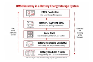
This structure allows operators to monitor battery health across the entire installation while identifying issues within specific modules or racks when needed.
What Does the BMS Actually Do?
The Battery Management System performs several important functions throughout normal operation.
Keeps Battery Cells Balanced
Battery cells naturally age at slightly different rates. Over time, some cells charge or discharge faster than others.
The BMS balances these differences to help maintain consistent performance across the battery pack. Balanced cells improve efficiency, support available capacity, and reduce unnecessary stress on the battery.
Estimates Available Capacity
The BMS also estimates State of Charge (SoC), which indicates how much usable energy remains in the battery.
It also tracks State of Health (SoH), a measure of how battery performance changes as the system ages. Together, these values help operators understand battery condition and plan maintenance more effectively.
Detects Problems Early
The BMS continuously monitors battery operation to detect abnormal conditions. Depending on the system architecture, the BMS may issue an alarm, apply operating limits, command contactors to open, or request a controlled shutdown. The level at which a fault can be isolated depends on the rack, contactor, fuse, and protection design. Prompt corrective action reduces the risk of larger failures and supports safe, reliable operation.
Power Conversion System (PCS): Moving Energy in Both Directions
Electrical energy is stored in the battery as direct current (DC), while the connected electrical infrastructure operates on alternating current (AC). Bidirectional power conversion is handled by the Power Conversion System (PCS), which converts electricity between DC and AC during charging and discharging.
In an AC-coupled system, the PCS converts AC electricity from the grid or an AC renewable source into DC during charging. In a DC-coupled solar architecture, battery charging may instead use a DC/DC conversion stage.
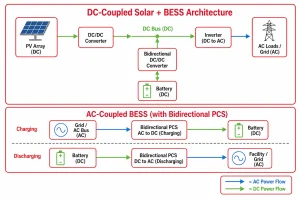
The quality of this conversion directly affects overall system efficiency. A reliable PCS helps maximize the value of stored energy while supporting stable operation under changing load conditions.
Grid Following and Grid Forming PCS
Not every BESS operates the same way during a grid outage.
A grid-following PCS works alongside an active utility grid. It synchronizes with the existing power supply and disconnects automatically if the grid becomes unavailable.
A grid-forming PCS can create its own stable voltage and frequency reference. This allows the battery system to continue supplying power to selected loads during outages or when operating as part of a microgrid. There is no single PCS configuration for every application. The operating profile of the facility determines whether grid forming or grid following functionality is more appropriate.
Energy Management System (EMS): The Brain Behind the Operation
The battery stores energy. The Battery Management System (BMS) protects it, and the Power Conversion System (PCS) controls how electricity moves in and out of the battery. The Energy Management System (EMS) brings everything together by deciding how and when the system should operate.
The Energy Management System (EMS) receives continuous input from the battery, electrical loads, renewable energy sources, utility tariffs, and operating schedules. The collected data allows the EMS to manage battery operation by selecting charging, discharging, or standby mode as required. Rather than reacting to a single event, the EMS looks at the overall operating conditions. This allows the system to balance performance, reliability, and energy costs throughout the day.
EMS commands remain subject to BMS safety limits, PCS operating limits, protection systems and site-controller logic. If an EMS requests an unsafe operating point, the lower-level safety and control systems must prevent it.
How the EMS Supports Daily Operations
Different facilities have different energy priorities. A manufacturing plant may focus on reducing demand charges, while a commercial building may want reliable backup power. The EMS can support both by adjusting how the battery is used.
BESS for peak shaving
One of the most common applications is BESS for peak shaving.
Electricity demand is not constant throughout the day. Short periods of high consumption often result in higher utility charges. The EMS monitors these demand spikes and instructs the battery to supply part of the required power when needed. Reducing peak demand helps businesses lower electricity costs without changing their day-to-day operations.
Time-of-Day Optimization and Grid Arbitrage Energy Storage
Electricity prices also change during the day in many regions due to time-of-day tariffs, where electricity rates vary based on demand periods. With energy arbitrage, the EMS charges the battery when electricity is less expensive or when excess solar energy is available. The stored energy is then used during higher-priced periods. This operating strategy allows businesses to make better use of available energy while improving overall operating efficiency.
Microgrid Operation
Many industrial sites combine battery storage with solar power and diesel generators.
The EMS coordinates these energy sources so they work together as one system. During a grid outage, it can help maintain power to critical operations while managing available energy as efficiently as possible.
Supporting Infrastructure: Cooling and Fire Protection
Battery reliability depends on the combined performance of electrical, thermal, and safety systems. Together, they support stable operation throughout the project’s service life. Well-controlled operating conditions help batteries perform consistently, while modern fire protection systems reduce risk if an unexpected event occurs.
Thermal Management
Heat is one of the biggest factors affecting battery performance and service life. As batteries charge and discharge, they naturally generate heat. If that heat is not managed properly, battery performance may gradually decline over time. Most commercial BESS projects use either air cooling or liquid cooling.
Air Cooling
Conditioned airflow regulates battery temperature in air-cooled systems. Because of their simpler design, they are often selected for smaller installations and applications with moderate ambient temperatures.
Liquid Cooling
Battery temperature is controlled in liquid-cooled systems by circulating coolant through dedicated cooling channels. These systems are commonly deployed in commercial and utility-scale projects with demanding operating conditions. The most suitable cooling method depends on factors such as project size, climate, operating conditions, and maintenance requirements.
Fire Detection and Protection
Modern Battery Energy Storage Systems are designed with multiple layers of protection.
Instead of relying on a single safety feature, different systems work together to detect abnormal conditions, isolate affected equipment, and reduce the impact of an incident.
Some common safety measures include:
- Battery enclosures incorporate gas detection systems that identify abnormal gas generation during the earliest stages of a fault.
- Automatic suppression systems help contain electrical fires and reduce damage to surrounding equipment.
- Pressure relief systems provide a controlled path for gas release when internal enclosure pressure increases.
These safety features work alongside the Battery Management System to support safe system operation.
Procurement Checklist for Project Teams
Selecting a Battery Energy Storage System involves much more than comparing battery capacity. A successful project depends on choosing equipment that matches operational requirements, integrates smoothly with existing infrastructure, and can support long-term business goals.
When evaluating suppliers, consider the following:
Battery Chemistry
Selecting the appropriate battery chemistry requires evaluating the operating profile, design life, and maintenance requirements of the project. Lithium Iron Phosphate (LFP) batteries are commonly chosen for commercial applications because of their thermal stability and long cycle life.
System Integration
Verify seamless communication between the Battery Management System (BMS), Power Conversion System (PCS), and Energy Management System (EMS). Seamless integration enables coordinated system control, improved operational visibility, and efficient lifecycle management.
Cooling Strategy
Review whether air cooling or liquid cooling is better suited to the project’s location, climate, and operating conditions.
Communication Standards
Open communication protocols such as Modbus TCP and CAN bus make it easier to integrate the BESS with existing monitoring platforms and future expansion projects.
Operational Requirements
Projects that require backup power during grid outages should verify whether the selected PCS supports grid-forming operation.
Final Thoughts
A Battery Energy Storage System (BESS) is much more than a collection of batteries. Every major component contributes to the overall performance of the system. The battery stores energy, the BMS protects it, the PCS manages power conversion, and the EMS coordinates daily operation.
A Battery Energy Storage System performs as a complete engineering solution rather than a collection of individual components. System reliability, efficiency, and service life depend on how effectively the battery, control systems, power conversion equipment, and supporting infrastructure operate together. Understanding these relationships supports more informed supplier selection and project planning.
References
- International Electrotechnical Commission (IEC). IEC 62933 Series: Electrical Energy Storage (EES) Systems. https://webstore.iec.ch/en/publication/67442
- International Electrotechnical Commission (IEC). IEC 62619: Safety Requirements for Secondary Lithium Cells and Batteries Used in Industrial Applications. https://webstore.iec.ch/publication/22940
- IEEE. IEEE Std 2686-2024: Recommended Practice for Battery Management Systems in Stationary Energy Storage Applications. https://standards.ieee.org/ieee/2686/12407/
- IEEE. IEEE Std 1547-2018: Interconnection and Interoperability of Distributed Energy Resources. https://standards.ieee.org/standard/1547-2018.html
- National Fire Protection Association (NFPA). NFPA 855: Standard for the Installation of Stationary Energy Storage Systems. https://www.nfpa.org/codes-and-standards/all-codes-and-standards/list-of-codes-and-standards/detail?code=855
- UL Solutions. UL 9540: Energy Storage Systems and Equipment. https://www.ul.com/services/energy-storage-system-testing-and-certification
- UL Solutions. UL 9540A: Test Method for Evaluating Thermal Runaway Fire Propagation in Battery Energy Storage Systems. https://www.ul.com/services/ul-9540a-test-method